

Understanding the Input Impedance Limitation of Inverting Amplifiers and Its Impact on Signal Amplification
2025-01-14 10:32:09 1160
We all know that an inverting amplifier can amplify an input signal inversely, this is very basic knowledge, and those who have studied electric circuits generally know it.
Inverting amplifier formula for Vout = - Vin * Rf / Rin. According to the known formula, can easily complete the design, but inverting amplifiers are born with a small defect, inverting the input amplifier's input impedance is not very high, and we generally hope that the amplifier's input impedance in the circuit design should be high, so that the amplifier will not be absorbed from the signal source current, so as not to affect the signal to be amplified! and have an effect on the amplification result of the circuit. Why is this so? Consider the following diagram of an inverting input amplifier (hereafter, an inverting input amplifier is referred to as an inverting amplifier).
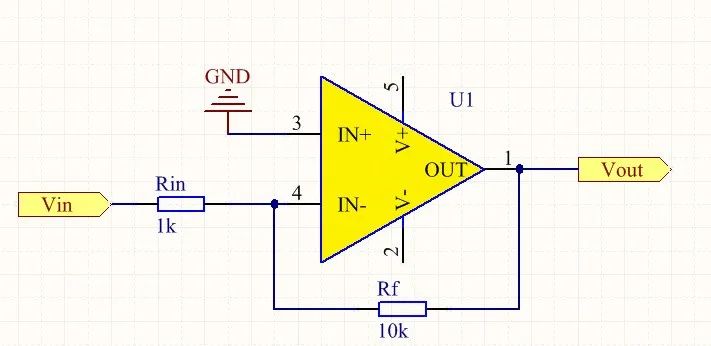
Figure. 1
According to the formula, Vout = -Vin*Rf/Rin, we know that the amplification is 10K/1K = 10 times. Well, please remember this result first.
The following according to the op-amp “virtual short virtual break” characteristics to analyze, the above figure with the phase input ground, the potential is 0, according to the characteristics of the op-amp virtual short, op-amp 3 feet with the phase input and 4 feet of the inverted input potential is equal, so 4 feet of the inverted input potential is also 0 potential. The right end of resistor Rin is equivalent to connecting to the 0 potential, and the op-amp equivalent Davignan circuit is shown below:
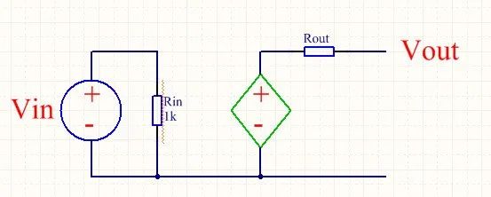
Figure. 2
Now imagine that we look at the entire amplifier circuit as a black box (figure below), we look from Vin this signal source to the inside of this black box, as can be seen from the figure below, this Rin determines the input impedance of the inverting amplifier, so the input impedance of this inverting amplifier is the size of Rin 1K.
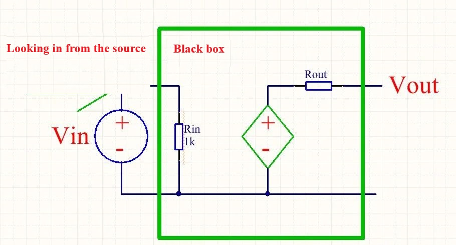
Figure. 3
Because of the existence of Rin, resulting in a low input impedance of the inverting amplifier, resulting in the inverting amplifier will have an impact on the signal source when working, thereby affecting the amplification results, here we come to talk about how the amplification of the inverting amplifier has an impact on the results? Our common signal source Vin, generally not an ideal voltage source, it will have internal resistance, assuming that the internal resistance of the signal source in the figure above for Rz, the size of 1K. According to this modified schematic diagram as follows:
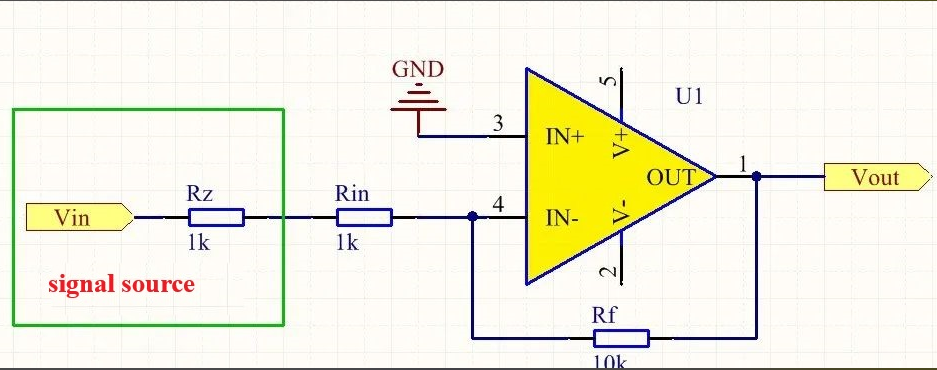
Figure. 4
As shown above, it can be clearly seen, the signal source internal resistance Rz and Rin is in series, according to the inverting amplifier formula, Vout = - Vin * Rf / (Rz + Rin), can be obtained as a result of 10k / (1k + 1k) = 5 times, remember the results of the beginning of the calculation? Isn't the amplification result 10 times? Yes, we envisioned the circuit is trying to amplify the input signal 10 times, and now the results are very different, the error is fully doubled, and the same circuit into a different internal resistance of the signal source, that is, Vin's internal resistance Rz is different, the amplification results will be different. Now you understand how this disadvantage of the inverting amplifier?
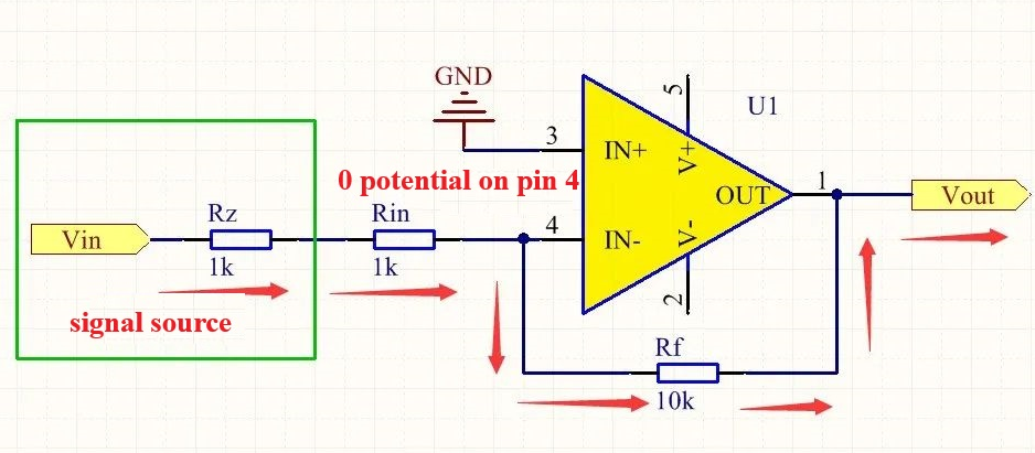
Figure. 5
Because the inverting input of the op-amp is 0 potential, according to the current flow in the above figure, you can easily determine the output Vout is a negative voltage, which is why there is a negative sign in front of the formula of the inverting amplifier, because the input voltage is inverted. Inverting the amplifier formula derivation, no longer here, according to the above current flow can also be easily derived from the formula.


