

Why PCB ground and metal chassis with a resistive connection?
2025-04-02 09:10:15 1093
Electronics grounding is a clichéd topic, the main content of this article is the metal casing and circuit board grounding issues. We often see some of the system design will be the PCB board ground (GND) and metal enclosure (EGND) between the usual use of a high-voltage capacitor C1 (1 ~ 100nF / 2KV) in parallel with a large resistor R1 (1M) connection. So why this design?
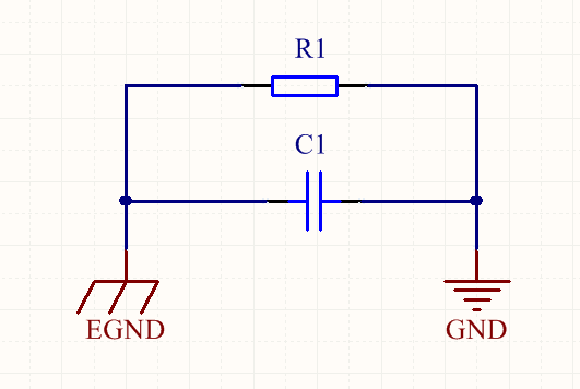
Fig. 1 Schematic diagram
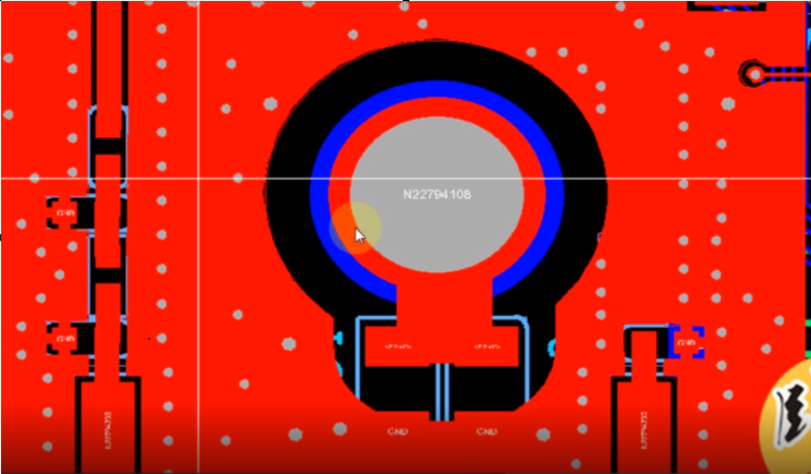
Figure. 2 Actual PCB
The role of capacitors
From the EMS (Electromagnetic Immunity) point of view, this capacitor, on the basis of ensuring that PE is connected to earth, is designed to reduce the effect on the circuit of possible high-frequency disturbing signals that are referenced to the earth's potential, thus suppressing the instantaneous common-mode voltage difference between the circuit and the source of the disturbance. In fact, it is ideal to connect GND directly to PE, but since a direct connection may lead to operational difficulties or safety hazards, for example, GND generated after a rectifier bridge cannot be directly connected to PE, a path was designed that prevents low-frequency signals from passing through but allows high-frequency signals to pass through. From an EMI (Electromagnetic Interference) point of view, if there is a metal case connected to PE, the existence of this high-frequency channel also helps to prevent high-frequency signals from being radiated to the external environment.
Capacitors are AC and DC resistors. Assuming that the chassis is well connected to the earth, from the point of view of electromagnetic immunity, the capacitance can inhibit high-frequency interference sources and circuits between the dynamic common-mode voltage; from the point of view of EMI, capacitance forms a high-frequency path, high-frequency interference generated by the circuit board inside the circuit board through the capacitance of the chassis flow into the earth, to avoid high-frequency interference to avoid the formation of the antenna radiation. Another situation, assuming that the chassis is not reliably connected to the earth (such as no ground, ground rod environment dry), the shell potential may be unstable or static electricity, if the circuit board directly connected to the shell, it will break the circuit board chip, adding capacitors, can be isolated from low-frequency high-voltage, static electricity, etc., to protect the circuit board. This parallel capacitance should be used Y capacitors or high-voltage film capacitors, capacitance value between 1nF ~ 100nF.
Role of Resistor
This resistor effectively prevents ESD (electrostatic discharge) damage to the board. If only a capacitor is used to connect the board ground to the case ground, the board constitutes a floating ground system. During ESD testing, or when used in complex electromagnetic field environments, the charge injected into the circuit board is difficult to be effectively released, and will accumulate; when it accumulates to a certain level, exceeding the voltage value that can be withstood by the weakest point of insulation between the circuit board and the enclosure, a discharge phenomenon will be triggered - in a very short period of time, tens to hundreds of amperes of current can be generated on the circuit board, and the circuit board will not be able to withstand it. In a very short time, the circuit board can generate tens to hundreds of amperes of current, which can cause the circuit to stop due to an electromagnetic pulse or destroy connected components near the site of the discharge. By installing this resistor, the charge is gradually released and the high voltage is eliminated. According to the IEC61000 ESD test standard, each discharge needs to complete the release of 2 kV within 10 seconds, so it is generally recommended to use 1 megohm to 2 megohm resistors. This high impedance component is also effective in reducing the current if the enclosure is charged with high voltage static electricity, thus preventing damage to the circuit chips.
Issues requiring attention
1, if the equipment shell good earth, then the PCB should also be a good single-point grounding with the shell, this time the frequency interference will be eliminated through the shell grounding, the PCB will not produce interference; 2, if the equipment used in the occasion there may be security issues, it must be a good grounding of the equipment shell; 3, in order to achieve better results, it is recommended that the equipment shell as good as possible to ground, the PCB and the shell of the single point of good ground; of course, if the shell does not have a high-voltage static electricity. Good grounding; of course, if the shell is not well grounded, it would be better to PCB floating ground, that is, not connected to the shell, because the PCB and the earth if it is isolated (the so-called floating ground), the industrial frequency interference loop impedance is very great, but will not produce any interference with the PCB;; 4, in a number of devices need to be connected to each other, it should be as far as possible to ensure that each piece of equipment shell and the earth in a single point for good grounding, while each Equipment internal PCB should also be grounded with its shell in a single point; 5, however, if more than one device connected to each other, the equipment shell can not achieve a good ground, then it will be turned into a floating state, the internal PCB does not need to be grounded to the shell instead of the more appropriate; 6, chassis ground may not be the ideal choice of ground, such as in the distribution network does not comply with the relevant safety regulations, there is no ground; or around the grounding bar Soil is too dry, grounding bolts appear rusty or loose. 7, the environment is the existence of electromagnetic interference, the working environment has a high-power transformers, high-power motors, electromagnetic furnaces, high-voltage grid harmonics, etc. 8, PCB internal is going to produce high-frequency noise, such as high-frequency switching tubes, diodes, storage inductors, high-frequency transformers and so on. These interfering factors will lead to PCB signal ground and chassis potential fluctuations (while containing high-frequency and low-frequency components), or the existence of static electricity between the two, so they are good and reliable grounding is necessary, but also the product safety requirements.


