

What should be considered when designing lightning protection circuits for power outlets?
2025-08-22 14:41:46 983
Factors to consider when designing lightning protection circuits for power outlets
The design of lightning protection circuits should meet the specified protection level requirements, and the residual voltage level of the lightning protection circuit should be able to protect downstream circuits from damage.
When subjected to lightning transient overvoltage, the protective device should have a sufficiently fast response speed, i.e., it should be able to limit voltage and divert current as early as possible.
The lightning protection circuit installed on the power supply line should not affect the normal power supply to the equipment. For example, when using a series-type power supply lightning protection circuit, the lightning protection circuit should be able to handle the current at full load operation of the equipment and have a certain margin.
The protective circuit should not activate at the system's maximum operating voltage. Typically, in AC circuits, the activation voltage of the protective circuit is 2.2 to 2.5 times the effective value of the AC operating voltage, while in DC circuits, the activation voltage is 1.8 to 2 times the DC rated operating voltage.
Lightning protection circuits installed on power supply lines should not pose safety hazards to equipment operation. For example, improper circuit design should be avoided to prevent safety hazards such as fire risks.
When multiple levels of lightning protection circuits are present along the entire power supply line, it is important to ensure that there is good coordination between the various levels of lightning protection circuits, and that the situation where the downstream lightning protection circuit is damaged by lightning while the upstream lightning protection circuit remains intact should not occur.
Lightning protection circuits should have functions such as damage alarm, remote signaling, thermal capacity, and overcurrent protection, and should be replaceable.
The following provides design guidelines for lightning protection circuits for AC power ports and DC power ports.
AC Power Port Lightning Protection Circuit Design
1. AC Power Port Lightning Protection Circuit
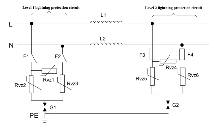
Figure. 1 AC Power Port Lightning Protection Circuit
The figure above shows a two-stage AC power port protection circuit:
G1 and G2 are gas discharge tubes
Rvz1 to Rvz6 are varistors
F1 and F2 are circuit breakers
F3 and F4 are fuses
L1 and L2 are decoupling inductors.
The circuit principle is briefly described as follows:
The first-level lightning protection circuit is a circuit with both common-mode and differential-mode protection. Differential-mode protection uses varistors. Common-mode protection uses varistors and gas discharge tubes in series. The first-level lightning protection circuit has a high current-carrying capacity, typically in the range of tens of kA (8/20 μs). The first-level lightning protection circuit should use circuit breakers as protective devices for short-circuit and overcurrent faults.
The second-level lightning protection circuit has the same configuration as the first-level circuit. By reasonably designing the inductance values between the first-level and second-level circuits, most of the lightning current can be diverted through the first-level circuit, with only a small portion flowing through the second-level circuit. This allows the residual voltage at the output of the lightning arrester to be further reduced through the second-level circuit, thereby protecting downstream equipment. The second-level lightning protection circuit should use fuses as protective devices.
The current-carrying capacity of each protective device in the protection circuit should meet the design specifications with a certain margin; the voltage-sensitive value of the differential mode voltage-sensitive resistor can be selected according to the methods provided in the voltage-sensitive resistor section; in the common mode protection circuit where the voltage-sensitive resistor and gas discharge tube are connected in series, the values of the voltage-sensitive resistor and air discharge tube can still be selected using the calculation methods provided in the relevant sections when the voltage-sensitive resistor and discharge tube are connected in parallel on the line.
Variations of AC Power Port Surge Protection Circuits
Variation Circuit 1
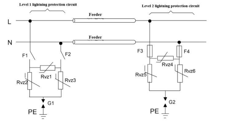
Figure. 2 Variation Circuit 1 for AC Power Port
Variation Circuit 1 replaces the inductor in the original circuit with a feeder line of a specified length. The inductance of the feeder line with the specified length is essentially the same as that of the inductor in the original circuit.
The advantage of replacing the inductor with a feeder line is that, under conditions of very high operating current for the equipment, selecting an appropriate feeder line diameter can meet the power supply requirements for the equipment, overcoming the issue of the inductor being too large to be implemented in the circuit when the power supply current is very high. The first-level protection circuit and the second-level protection circuit can be implemented in two separate devices, for example: the first-level protection circuit can be designed as an independent lightning protection box, while the second-level lightning protection circuit can be built into the communication equipment.
Since the inductor has been removed, Variant Circuit 1 can be regarded as two parallel lightning protection circuits. When these two levels of lightning protection circuits are made into two separate lightning protectors, attention must be paid to the installation of the lightning protectors.
Variant Circuit 2
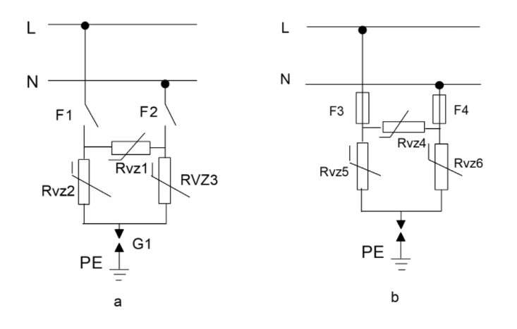
Figure 3 AC Power Port Variant Circuit 2
Variant Circuit 2 is a simplified design of the AC lightning protection circuit: only the first-level or second-level lightning protection circuit is retained, with other design considerations identical to the AC power port lightning protection circuit.
Circuit a is used when the downstream circuit has strong surge overvoltage protection capabilities, while Circuit b is used when external first-level protection measures are present, typically designed within the power module. Variation Circuit 2 reduces circuit complexity and, since the inductor is removed, there is no need to consider meeting the requirements for normal operating current through the equipment, making the design easier to implement. Since the inductor is removed, this circuit transforms from a series lightning protection circuit to a parallel lightning protection circuit. When this circuit is made into an independent lightning arrester, attention must be paid to the installation of the lightning arrester.
DC Power Port Surge Protection Circuit Design
DC Power Port Surge Protection Circuit
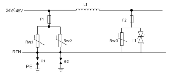
Figure. 4 DC Power Port Surge Protection Circuit
The above figure shows a circuit with a two-stage differential mode protection circuit in series, capable of handling a nominal discharge current of 5kA. The circuit principle is briefly described as follows:
The first stage employs differential mode protection using two varistors in parallel, while common mode protection is provided by two gas discharge tubes in parallel (Note: The use of two devices in parallel is intended to reduce residual voltage and increase current-carrying capacity; if a single device meets the requirements, only one device may be used). This configuration achieves the design specification of a nominal discharge current of 5kA. The second stage uses varistors and TVS diodes for protection, reducing the residual voltage to a level that the downstream circuit can withstand. The TVS diode T1 is recommended to use a bidirectional TVS diode, which can prevent reverse connection, or a unidirectional TVS diode can be used, but it has the drawback of not preventing reverse connection. Common-mode protection uses a first-stage protection circuit composed of two gas discharge tubes in parallel.
The advantage of this circuit is its low output residual voltage, making it suitable for situations where the downstream circuit has a very low overvoltage withstand capability. The selection of current-carrying capacity, varistor voltage, reverse breakdown voltage for each protective component in the lightning protection circuit, and the value of the inductor can be determined using the methods outlined in the relevant sections. Both levels of the lightning protection circuit should use fuses as protective devices.
This protection circuit is applied in scenarios where the downstream circuit has weak surge overvoltage resistance, and the first-level lightning protection circuit is insufficient to protect the downstream equipment, requiring the second-level lightning protection circuit to further reduce the residual voltage.
Variation of the DC power supply port lightning protection circuit
Variation circuit 1
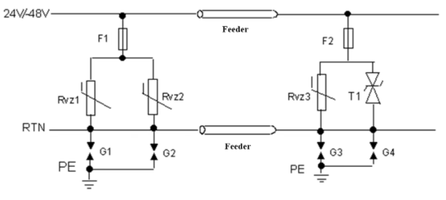
Figure. 5 Variation circuit 1 for the DC power supply port
Variation circuit 1 replaces the inductor in the DC power supply port lightning protection circuit shown in Figure 6-4 with a feeder line of a specified length. The inductance of the feeder line of the specified length is essentially the same as that of the inductor in the original circuit.
The advantage of replacing the inductor with a feeder line is that, under conditions of very high operating current for the equipment, selecting an appropriate feeder line diameter can meet the power supply requirements for the equipment, overcoming the issue of the inductor being too large to be implemented in the circuit when the power supply current is very high. The first-level protection circuit and the second-level protection circuit can be implemented in two separate devices, for example: the first-level protection circuit can be designed into a DC high-impedance cabinet, and the second-level lightning protection circuit can be built into communication equipment.
Since the inductor has been removed, Variant Circuit 1 can be considered as two parallel lightning protection circuits. When these two levels of lightning protection circuits are made into two separate lightning arresters, attention must be paid to the installation of the lightning arresters.
Variant Circuit 2
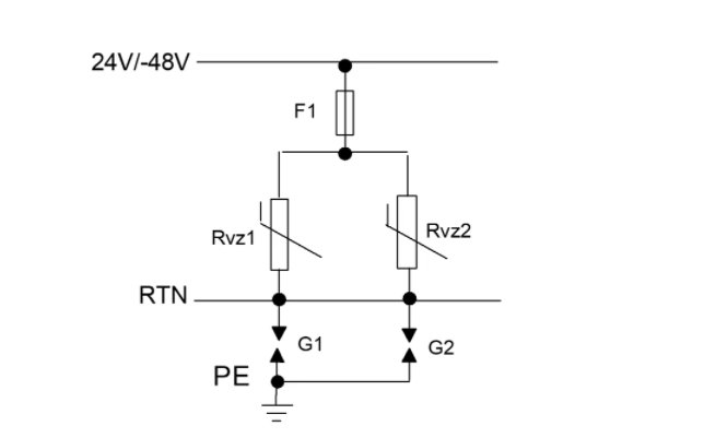
Figure. 6 DC Power Port Variant Circuit 2
Variant Circuit 2 is a simplified design of the DC power port lightning protection circuit: it retains the first-level lightning protection circuit (note: the purpose of using two devices in parallel is to reduce residual voltage and increase current-carrying capacity; if a single device meets the requirements, only one device can be used), while removing the inductor and the second-level lightning protection circuit. Other design considerations are the same as for the DC power port lightning protection circuit.
Variant Circuit 2 is applicable when the downstream circuit has strong surge overvoltage protection capabilities, as this design reduces circuit complexity. Additionally, since the inductor is removed, there is no need to consider the requirement for normal operating current, making the design easier to implement. Since Variant Circuit 2 removes the inductor, it transforms from a series lightning protection circuit to a parallel lightning protection circuit. When this circuit is implemented as an independent lightning arrester, attention must be paid to the installation of the lightning arrester.


