

What comprehensive protection mechanisms does the OTP series offer?
2025-08-27 15:50:28 1096
Yageo's OTP series of over-temperature protection fusing resistors represents a new generation of protective components. Featuring both over-temperature and over-current protection capabilities, these resistors are primarily used in high-computing or high-temperature/high-voltage industries such as power supplies, home appliances, lighting, charging equipment, and industrial machinery—where resistors require higher-specification safety protection mechanisms. When overcurrent occurs in the circuit, the OTP series fuses and opens within a specified timeframe, preventing faults and protecting components from damage.
The OTP series integrates a thermal fuse (Thermal-link) within the resistor, forming a series structure between the resistive wire and the thermal fuse. When the resistor's operating temperature or ambient temperature exceeds the thermal fuse's melting point, the thermal fuse melts, interrupting the circuit. This product effectively addresses the drawback of conventional wire-wound fuses generating persistent abnormal high temperatures during minor faults or small overload currents.
Current conventional protection methods employ two components—NTC (thermistor) and FUSE (fuse)—for thermal surge protection. The OTP series, however, offers a more comprehensive protection mechanism within a single component: FUSE function + thermal fuse function + short-circuit protection + cold-state and hot-state surge protection + voltage division and reduction.
Over-temperature protection is an electronic safeguard designed to shield circuits and equipment from high-temperature damage. When the circuit or device exceeds a preset temperature, the over-temperature protection automatically disconnects the power supply or reduces power to prevent further heating.
Functional Principle: Overvoltage protection primarily prevents output voltage from exceeding a predetermined maximum value. Internal voltage detection circuits continuously monitor output voltage. When output voltage exceeds the set range, the overvoltage protection mechanism activates. This may involve adjusting the duty cycle of the switching power supply (for PWM-type units) to reduce output voltage, or in extreme cases, cutting off the output to protect connected load devices from damage due to excessive voltage.
Application Scenarios and Importance: In certain situations, such as internal feedback loop failures or external interference causing voltage regulation to malfunction, the output voltage may abnormally rise. Many electronic devices have limited tolerance for input voltage variations, and overvoltage can damage electronic components like integrated circuit chips and capacitors. Overvoltage protection ensures these devices remain undamaged by excessively high voltages.
Traditional over-temperature protection circuits utilize the temperature characteristics of bipolar transistors to monitor chip operating temperature. A current proportional to temperature flows through a resistor, generating a temperature detection voltage. A voltage comparator then compares this temperature detection voltage against a system-set, non-temperature-dependent bandgap reference voltage. When the temperature detection voltage exceeds the bandgap reference voltage, the chip system shuts down, achieving over-temperature protection [3]. Here, IP1 and IP2 represent positive temperature coefficient currents. At normal temperatures, OTP_OUT outputs a high level, causing NMOS transistor M1 to conduct and short-circuit resistor R2, resulting in VNVP. When OTP_OUT outputs a low level, the over-temperature protection circuit shuts down other modules. At this point, transistor M1 turns off, and VN = IP1 · (R1 + R2). As the operating temperature gradually decreases, VN also decreases.
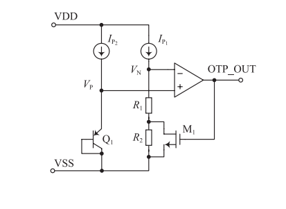
Figure 1. Schematic Diagram of Traditional Over-Temperature Protection Circuit
Based on the 0.25 μm BCD process library, a high-precision, low-power over-temperature protection circuit is proposed. It utilizes the temperature characteristics of bipolar transistors to detect system temperature and implement over-temperature protection shutdown functionality, replacing the traditional voltage comparator architecture. The circuit features a simple structure and low power consumption. At normal temperatures, OTP_OUT outputs a low level, causing NMOS transistor M1 to conduct. R2 is shorted, resulting in VE = IP1R1 and VEVBE. Transistor Q1 enters deep saturation, shifting its collector voltage from low to high. OTP_OUT then outputs a high level, activating the over-temperature protection function. At this point, transistor M1 turns off, and VE = IP1 · (R1 + R2). When the temperature drops below the critical threshold, the electronic load should maintain full protection functionality. Protection functions are categorized into internal (electronic load) protection and external (device under test) protection. Internal protection includes: overvoltage protection, overcurrent protection, overpower protection, reverse voltage protection, and overheat protection. External protection includes: overcurrent protection, overpower protection, load voltage protection, and undervoltage protection. When selecting an electronic load, choose one with genuine protection capabilities. If implemented via hardware, protection response is extremely fast. Software-based implementation introduces latency, posing significant risks if the module crashes.
Over Temperature Protection (OTP) is a common electronic safeguard typically employed to shield circuits and electronic devices from high-temperature damage. When the temperature of a circuit or device rises above a preset threshold, OTP automatically triggers to control the temperature drop by disconnecting the power supply or limiting the current, thereby preventing further heating.
OTP can be implemented through various methods, depending on application requirements and design principles. Common approaches include:
Software Implementation: System software controls circuit or device actions, automatically triggering protective measures upon detecting excessive temperatures.
Hardware Implementation: Integrated circuits or other electronic components monitor circuit or device temperatures, cutting power or limiting input current when preset thresholds are reached.
PTC Thermistor-Based: In specialized electronic devices, PTC thermistors with temperature-responsive characteristics are used to implement over-temperature protection.
When an electronic device triggers over-temperature protection, try these steps to resolve the issue:
Check Temperature: First confirm whether the device is overheating and identify the cause. Reduce Power: If the device is overloaded or used excessively frequently, limit the input power. This helps lower the device temperature and prevent overheating. Airflow: If the device is in an enclosed or poorly ventilated environment, add ventilation openings or implement other methods to improve air circulation. Relocate: If the device is positioned near a heat source or in an excessively warm location, move it to a cooler area. Repair or Replace: When overheating protection is triggered due to device malfunction, identify the root cause and perform repairs, or consider replacing the device.


