

How to Accurately Measure Power Supply Ripple Noise: Probe Selection, Grounding, and Bandwidth Tips
2025-06-13 10:44:48 922
A user was testing the ripple of a 5V signal output from a switching power supply using an oscilloscope with a 500MHz bandwidth. They found that the peak-to-peak value of the ripple and noise reached over 900mV (as shown in the figure below), while the switching power supply's specified peak-to-peak ripple value was <20mV. Although the user's circuit board had an LDO at the output stage to further regulate the voltage from the switching power supply, the user believed the measured result was too high and not credible, and hoped to identify the root cause of the issue.
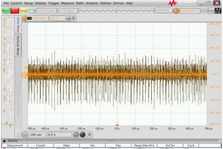
Figure. 1
Problem Analysis
Excessively high power supply ripple test results are typically related to the probe used and the connection method at the front end. First, the user's probe connection method was inspected, and it was found that a long alligator clip ground wire was used, as shown in the left figure below, with the ground point clamped to the PCB's mounting screw, resulting in a relatively large ground loop. Since a large ground loop introduces more spatial electromagnetic radiation noise and ground loop noise caused by the switching power supply, it was replaced with a short grounding spring pin, as shown in the right figure below.
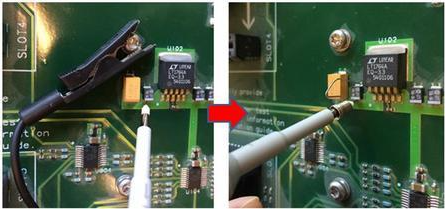
Figure. 2
Through actual testing, it was found that the peak-to-peak value of the measured ripple noise improved significantly, as shown in the figure below. However, the peak-to-peak value of the ripple noise was still over 40 mV, which was still significantly different from the switch-mode power supply manufacturer's specified value of <20 mV.
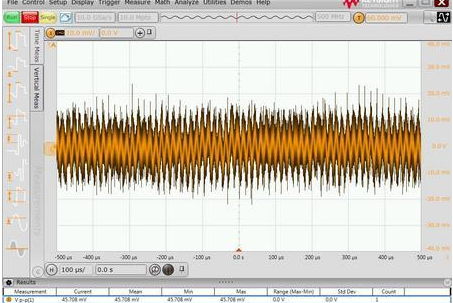
Figure. 3
Further inspection of the probe model used by the user revealed that the user was using the standard 10:1 passive probe included with the oscilloscope. As shown in the figure below.
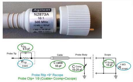
Figure. 4
A 10:1 probe attenuates the measured signal by a factor of 10 before sending it to the oscilloscope, which then performs a 10x mathematical amplification on the signal. The advantage of this probe is that the matching circuit at the front end enhances the probe bandwidth to several hundred MHz and extends the oscilloscope's range. However, it is not particularly advantageous for measuring small signals. If the amplitude of the measured signal is already small, further attenuation by a factor of 10 may cause it to be drowned out by the oscilloscope's baseline noise. Even with an additional 10x mathematical amplification, this does not improve the signal-to-noise ratio. Therefore, for measuring power supply ripple noise, it is preferable to use probes with a smaller attenuation ratio, such as a 1:1 probe. Therefore, another 1:1 passive probe was used. Although this 1:1 passive probe has a relatively low bandwidth (typically several tens of MHz), its low attenuation ratio makes it highly suitable for small-signal testing.
The figure below shows the comparison test results between the 1:1 passive probe and the 10:1 probe under different bandwidth restrictions. As can be seen, when using the 1:1 probe with a 20 MHz bandwidth restriction, the measured ripple noise peak-to-peak value is less than 10 mV, significantly better than the results from the 10:1 probe. The test results from the 1:1 probe clearly show the ripple waveform and meet the user's expectation of power supply ripple noise <20 mV. Additionally, we can see that the bandwidth limit also has a certain improvement effect on the noise peak-to-peak value.
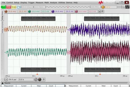
Figure 5
Problem Summary
This is a typical issue in power supply ripple testing. By using a short ground connection, switching to a probe with a low attenuation ratio, and applying the bandwidth limit function, the test results for ripple noise were significantly improved. Generally, the factors affecting power supply ripple test results, ranked by importance, are as follows:
Length of front-end connection cables and ground loops: Long ground loops pick up more electromagnetic radiation from switching power supplies and ground noise, so it is necessary to use the shortest possible ground connection.
Probe attenuation ratio: Probes with high attenuation ratios can make small signal amplitudes even weaker, potentially being drowned out by the oscilloscope's baseline noise. Therefore, probes with a 1:1 attenuation ratio should be used whenever possible.
Bandwidth limiting: Many electromagnetic noises and oscilloscope baseline noises are broadband in nature. Setting an appropriate bandwidth limit can filter out additional noise. Many power supply ripple noise test scenarios use a 20 MHz bandwidth limit, while some chips may require measurements up to 80 MHz or 200 MHz.
Measurement range: Power supply ripple tests are typically conducted at lower ranges (e.g., 10 mV/div or 20 mV/div). The larger the range, the higher the oscilloscope's baseline noise. However, some oscilloscopes have limited offset ranges, and at lower ranges, they may not be able to pull the measured DC voltage signal back to the center of the screen for measurement. Therefore, the oscilloscope's AC coupling function is often used to isolate the DC signal before performing ripple noise testing.
Input impedance: Many oscilloscopes offer input impedance options of 50 ohms and 1 M ohms. Typically, the oscilloscope's baseline noise is lower at 50 ohms input impedance. However, when connecting most passive probes, the oscilloscope automatically switches the impedance to 1 M ohms. The input impedance can only be set to 50 ohms when connecting active probes or coaxial cables.


