

Convergence and Trade-off between Floating Point and Fixed Point - Local Floating Point Optimization Design Based on IIR Filters
2025-03-10 11:55:57 1320
The most widely used data type that ensures high-precision computing for modeling and simulating algorithms is floating-point. In order to preserve hardware resources and expedite computation, the only way to implement these floating-point algorithms on FPGA or ASIC technology is to transform each data type in the algorithm to fixed-point. It can occasionally be challenging to achieve the ideal balance between word length and mathematical accuracy of a data type during conversion, and switching to fixed-point diminishes mathematical precision. Fixed-point conversion might require weeks or months of engineering work for calculations that need high dynamic range or high precision (such as those with feedback loops). Additionally, designers need to use huge fixed glyphs to ensure digital precision.
This study will present the Math Works intrinsic floating-point application workflow for ASIC/FPGA filter design. The difficulties of using fixed-point will then be reviewed, and the use of single-precision floating-point with frequency tradeoffs will be compared. fixed point. We'll also demonstrate how, in practical designs, combining floating-point and fixed-point can increase accuracy while cutting down on conversion and implementation time. Contrary to the widespread assumption that fixed point is always more economical than floating point, you will show the importance of modeling directly in floating point and how it may greatly reduce area and boost performance in real-world designs with high dynamic range needs.
Native Floating Point Implementation: Under the Hood
The single-precision algorithm is implemented by the HDL encoder, which simulates the underlying arithmetic using FPGA or ASIC resources (Figure 1). The input floating-point signal is decoded by the created logic into sign, exponent, and mantissa-single integers with widths of 1, 8, and 23 bits, respectively.
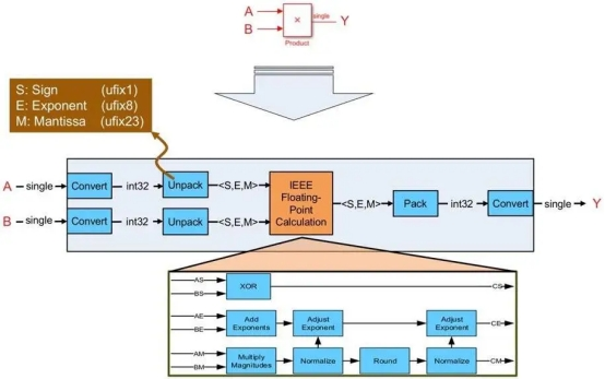
Figure 1. How the hdl encoder maps a single-precision floating-point multiplication to fixed-point hardware resources
The created vhdl or Viilog logic then computes the sign bits produced by the input sign bits, the number multiplication, and the exponent needed to compute the result and the associated normalization in order to conduct a floating-point computation (multiplication in the case depicted in Figure 1). The sign, exponent, and mantissa are packed back into the floating-point data type in the last step of the logic.
Solving Dynamic Range Problems with Fixed-Point Conversions
Single-precision floating-point can naturally convert a basic equation that must be implemented over a wide dynamic range, like (1-A)/(1+A) (Figure 2).
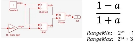
Figure 2. Single-precision implementation of (1-a)/(1+a)
However, there are numerous steps and numerical considerations involved in implementing the same equation at a fixed-point (Figure 3).
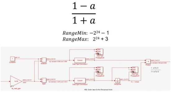
Figure 3. Fixed-point implementation of (1-a)/(1+a)
For instance, you need to separate division into reciprocity and multiplication, use Newton-Raphson or LUT (look-up table) approximation methods for nonlinear reciprocal operations, carefully control bit growth using different data types, select the right numerator and denominator types, and use particular output and accumulator types for expansions and subtractions.
Exploring CIR implementation options
Let's examine an infinite impulse response filter example. Converging to a fixed point of quantization is challenging for an IR filter because it necessitates high dynamic range computing with a feedback loop. Three iterations of the same IRR filter with a noisy sine wave input are compared in the test setting depicted in Figure 4A. The sine wave has an amplitude of 1, which is slightly increased by the additional noise.
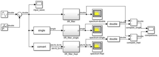
Figure 4A. Implementation of three ir filters with noisy sine wave inputs.
Double precision is the initial iteration of the filter (Figure 4B). Single precision is the second variant. A fixed-point realization is the third version (Fig. 4C). A data type of up to 22 bits is produced by this implementation, with 21 bits going to the fraction and one bit going to the sign.
Since a stimulus will always have a value range between -1 and 1, this specific data type leaves 0 bits to represent integer values, which makes sense. The quantization of the fixation points must account for the requirement that the design employ varied input values.
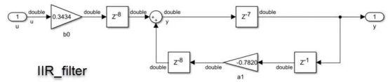
Figure 4B. Effect of IIR filter using double-precision data type.
Figure 4C. Effect of IIR filter using fixed-point data type.
The double-precision filter, which is regarded as the gold standard, was used to compare the outcomes of the single-precision and fixed-point filters in a test environment. Error results from the loss of precision in both situations. Whether the error falls inside our application's allowable tolerance is the question.
We set an error tolerance of 1% when we used Fixed Point Designer to carry out the conversion.
The comparison findings are displayed in Figure 5. The fixed-point data type has an error of roughly 10 -5, but the single precision variant has an error of roughly 10. -8. This is within the range of errors we have given. You might want to adjust the set word length if your application calls for greater precision.
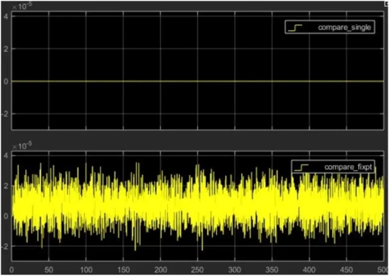
Figure 5. Comparison of simulation results
The IIR filter results for the double-precision and single-precision implementations are contrasted in the top figure, and the results for the double-precision and fixed-point implementations are contrasted in the bottom figure.
This type of quantized fusion necessitates precise precision requirements, a solid grasp of potential system inputs, hardware design skill, and some assistance from the fixed-point designer. The effort will be justified if this aids in refining the algorithm for production deployment. However, what about scenarios that call for straightforward hardware prototype deployment or where minimizing the physical footprint is challenging due to accuracy requirements? Using single precision local floating point is one way to deal with these situations.
Simplifying the Process with Native Floating Point
The use of native floating point has two benefits.
You don't have to waste time attempting to determine how many bits are needed to maintain sufficient accuracy for a wide range of input data.
- At a fixed cost of 32 bits, the dynamic range of single-precision floating-point operations is more effective.
The design process is now considerably easier, and you are aware that a large dynamic range of numbers can be represented using sign, exponent, and tail bits. The floating-point resource usage with the data type selection in Figure 5 and the fixed-point implementation of the ir filter are contrasted in the table in Figure 6.
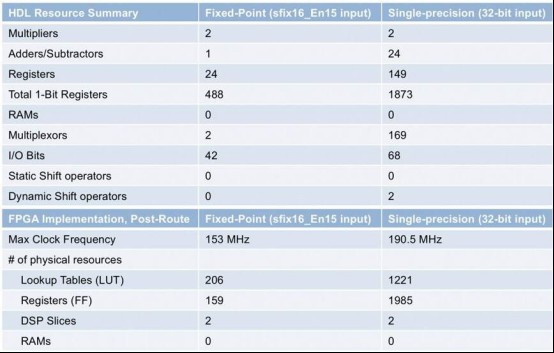
Figure 6. Comparison of resource utilization for fixed-point and floating-point implementations of the ir filter
Remember that floating-point computations take more operations than straightforward fixed-point algorithms when comparing the outcomes of the floating-point and fixed-point implementations. When implemented to an FPGA or ASIC, single precision will use more physical resources. Higher precision and resource usage will have to be sacrificed if circuit area is a concern. You can also use a combination of floating-point and fixed-point to reduce area while maintaining single precision to achieve high dynamic range for digitally intensive computations.


